

How to Use a Power Supply Unit with a Multimeter to Verify Voltage Output Accurately.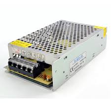
Whether you are building your first DIY electronics project, calibrating workbench equipment, or troubleshooting a malfunctioning circuit, verifying your power supply unit (PSU) output is one of the most fundamental skills in electronics.
Relying solely on a power supply's built-in digital display or an adjustable knob's dial markings can be a recipe for disaster. Components like microcontrollers, ICs, and sensitive sensors often have strict voltage tolerances. Supplying even a fraction of a volt too high can instantly destroy sensitive hardware, while an under-voltage supply can cause confusing system resets and erratic behavior.
In this practical guide, we will show the step-by-step how to use a digital multimeter (DMM) to accurately verify PSU output, observe real-time voltage fluctuations, and test stability under load conditions.

Why You Should Never Skip Manual Voltage Verification
Most variable benchtop power supplies feature built-in voltage LED displays. While these built-in meters are fine for rough estimates, they aren't always 100% accurate. Over time, internal calibration can drift, or cheap power adapters may sag under load.Measuring output independently with a multimeter gives you three important advantages:
- Precision: A quality digital multimeter provides higher resolution (often down to millivolts).
- Real-Time Load Response: You can observe if your PSU output sags when your circuit draws more current.
- Safety Insurance: You confirm that no hidden over-voltage spikes reach your expensive prototype components.
Equipment and Setup Checklist
To follow along with this demonstration, ensure you have the following gear ready on your workbench:
| Equipment | Recommendation / Setting |
| Power Supply Unit (PSU) | Benchtop DC supply, wall adapter, or PC ATX power supply |
| Digital Multimeter (DMM) | Standard manual-ranging or auto-ranging multimeter |
| Test Probes | Standard needle probes or insulated alligator clip leads |
| Test Load (Optional) | Power resistor or dummy load for stability testing |
Step-by-Step Guide: Measuring the DC Voltage Output
Step 1. Configure Your Multimeter Ports: Crucial step to prevent short circuits or blown the fuse:
Insert the black probe lead into the COM (Common) port on your multimeter. Next, plug the red probe lead into the port labeled V/Omega/mA (Voltage/Resistance).Warning: Never plug the red lead into the 10A or 20A high-current jack when measuring voltage—doing so creates a direct short across the power supply!
Step 2. Select the Correct Measurement Mode:
Turn your multimeter dial to DC Voltage (indicated by a capital V with a solid line over a dashed line)- If using an Auto-Ranging Meter: Simply set it to DC Voltage.
- If using a Manual-Ranging Meter: Select a range higher than your expected maximum voltage (e.g., set to the 20V range if testing a 5V or 12V rail).
Step 3. Connect Probes to the Power Supply Terminals:
Power on your PSU with no circuit attached. Touch or clip the black probe to the negative (- ) or Ground terminal and the red probe to the positive (+) terminal.If your leads are reversed, your multimeter will display a negative sign (e.g., -12.0\V), but this will not damage a digital meter.
Step 4. Observe Open-Circuit Output Voltage:
Read the measurement on your multimeter display. Adjust your bench supply dial and compare the voltage on the PSU screen against the multimeter reading. Note any discrepancy between the two devices.Step 5. Test Voltage Stability Under Load:
Connect your load (or a suitable power resistor) to the power supply alongside your multimeter probes. Watch for voltage sag as current starts flowing. A good, regulated power supply should maintain a steady output with minimal drop.
Understanding Voltage Fluctuations and Ripple
When observing your multimeter display during load testing, you may see the last digit fluctuating slightly. Here is what those readings mean:- Minor Fluctuations (+-0.01V - 0.05V): Completely normal digit flicker on high-resolution multimeters.
- Significant Sag (> 0.5V drop under load): Indicates the power supply is reaching its current limit or has poor voltage regulation.
- Drifting Output: If the voltage continuously drops or rises over time, the PSU internal components may be overheating.
Common Mistakes to Avoid
- Using AC Mode for DC Measurement: Setting the dial to AC (-V) while measuring a DC supply will give inaccurate or zero readings.
- Leaving the Meter in Current (Amp) Mode: Ammeters have nearly zero internal resistance. Connecting meter probes in current mode across a power supply will spark and blow your multimeter fuse instantly.
- Exceeding Meter Ratings: Always double-check your multimeter's maximum input rating before measuring high-voltage sources.
Conclusion & Next Steps
Verifying your power supply unit with a multimeter is a quick 2-minute habit that saves hours of frustrating troubleshooting down the road. By mastering these probe connections, meter settings, and load observation techniques, you ensure your circuits always receive clean, accurate power. What test equipment or troubleshooting tool would you like to see demonstrated next on the bench? Drop a comment down below with your suggestions!
If you found this breakdown helpful, don't forget to subscribe for weekly electronics testing guides, tool demonstrations, and benchtop techniques.