

WHAT IS JUANFI PISOWIFI?

💻Decoding the PISO Wi-Fi Ecosystem: An In-Depth Look at JuanFI and MikroTik Integration
The Piso Wi-Fi Vendo business model thrives on providing affordable, coin-based internet access.
I. JuanFI: The Open-Source Engine for Wi-Fi Vendo
JuanFI is a free and open-source software platform developed to manage and automate the operations of a Wi-Fi Vendo (coin-operated internet vending) machine.
The Open-Source Advantage
The core mission of JuanFI, as stated by its developer Ivan Julius Alayan, is to increase digital inclusion by rapidly deploying vendo machines in underserved communities. Its open-source nature provides critical advantages:
Cost-Effectiveness: It eliminates proprietary licensing fees, significantly lowering the barrier to entry for small entrepreneurs.
Community-Driven Development: The code is transparent, allowing developers to audit, improve, and add features based on real-world operational needs and troubleshooting.
High Customization: Operators can modify the captive portal's look, feel, and features to better suit their local market or branding.
II. The Technical Marriage: JuanFI and MikroTik
JuanFI's design is intrinsically linked to the MikroTik RouterOS platform. MikroTik routers are highly favored in the PISO Wi-Fi industry due to their affordability, stability, and powerful feature set, particularly their built-in Hotspot Gateway functionality.
How JuanFI Works with MikroTik
JuanFI essentially operates as the billing and control layer that sits on top of the MikroTik's robust networking layer.
MikroTik's Role (The Enforcer): The MikroTik router is configured to direct all client traffic to its built-in Hotspot Gateway. It manages the underlying network protocols, traffic shaping, and firewall rules.
JuanFI's Role (The Controller): When a user connects to the Wi-Fi, the router directs them to the JuanFI Captive Portal. JuanFI authenticates the user's coin deposit, generates a time-based voucher (or token), and communicates this voucher back to the MikroTik router via its API (Application Programming Interface).
Authentication & Billing: The MikroTik uses the voucher generated by JuanFI to grant access for the specific amount of time purchased, automatically cutting off access once the time expires.
This architectural separation allows the operator to leverage the stability of MikroTik for networking while enjoying the flexible, user-friendly interface of JuanFI for customer interaction and billing.
III. Essential Features and Business Optimization
A key differentiator for high-quality hotspot software is the range of features it offers to maximize profitability and user experience. JuanFI provides several critical components:
Customizable Captive Portal: The login page is fully editable, allowing the vendor to display local promotions, announcements, and clear pricing tiers (e.g., ₱1 for 6 minutes, ₱5 for 30 minutes).
Bandwidth Management: JuanFI allows operators to define specific speed limits for different pricing tiers (e.g., higher speed for a ₱10 purchase versus a ₱1 purchase), ensuring fair access and preventing network hogging. This is done by manipulating the Simple Queues feature within RouterOS.
Voucher Generation and Reporting: The system enables the printing or digital generation of vouchers (for non-coin operation) and provides detailed sales reports, tracking daily cash flow, peak usage times, and overall system profitability.
IV. Conclusion: Driving Digital Inclusion
JuanFI represents a significant technological enabler in the Philippine micro-enterprise sector. By leveraging the low-cost, high-performance capabilities of MikroTik and providing a free, adaptable software layer, it empowers small business owners to provide necessary internet access to communities. The system's success is a direct measure of its effectiveness in closing the digital divide by making internet connectivity affordable and ubiquitous.
WHAT IS MIKROTIK?
🌐 Deep Dive into the MikroTik Hotspot: Architecture, Security, and Advanced Access Control
The MikroTik Hotspot is a sophisticated Wireless Access Gateway (WAG) component integrated into RouterOS, designed to manage and monetize network access. It functions by implementing a captive portal—a forced authentication layer—that intercepts client traffic and directs it to a controlled login environment.
I. The Hotspot Technical Workflow
The effectiveness of the MikroTik Hotspot lies in its ability to transparently intercept and redirect traffic at the network layer.
1. Packet Interception and Redirection
When an unauthenticated client connects, the Hotspot utilizes dynamic firewall rules injected into the router's packet flow.
Initial Connection: The client obtains an IP address via DHCP from the Hotspot server's range.
DNS Redirection: All DNS requests are forced to the router's internal DNS server. This is a critical step because the router manipulates the DNS response for the client's first non-whitelisted request, sending back the IP address of the Hotspot server itself.
The Captive Portal Trigger: Any attempt by the client to access a web page (HTTP/HTTPS) is captured by Destination NAT (DNAT) rules. The traffic is redirected to the Hotspot server's built-in web proxy, which displays the
login.htmlpage.
2. The Walled Garden
Before successful authentication, the client is placed in the Walled Garden. This is a whitelist of domains, subnets, and ports that clients are allowed to access without logging in.
Essential Inclusions: The Walled Garden must permit access to the Hotspot server's IP, the DNS server, and, crucially, any external authentication servers (e.g., a third-party RADIUS server or payment gateway domains) to allow the login process to function. Administrators use the
/ip hotspot walled-gardenand/ip hotspot walled-garden iplists for this configuration.
II. Security and Authentication Methods
Security is paramount in public networks. The MikroTik Hotspot allows administrators to select authentication methods based on their security needs.
| Authentication Method | Protocol | Security Implication | Use Case |
| HTTP PAP | Plain-text (unencrypted) | LOW: Credentials are sent over the network as plain, readable text. | Only safe if the login page is secured with a valid SSL/TLS certificate (HTTPS). |
| HTTP CHAP | MD5 Hash | MEDIUM: Password is never sent directly; a hash is used. However, MD5 is considered outdated and weak. | Legacy systems or basic security requirements without full SSL/TLS. |
| RADIUS | External Server | HIGH: Centralized user management, dynamic policy enforcement, and integration with modern protocols (often required for advanced features like 802.1X). | Enterprise, ISP, and large-scale commercial deployments. |
Security Best Practice: A professional setup requires using HTTPS for the login portal. This necessitates obtaining and importing a trusted SSL certificate into the router's certificate store (/system certificate), which ensures all submitted passwords are encrypted.
III. Advanced Control and Customization
The true utility of the MikroTik Hotspot lies in the granular control it offers over user sessions and the network brand.
1. User Profiling and Dynamic Queues
Administrators define User Profiles under /ip hotspot user profile. These profiles are the blueprint for the user experience, allowing for powerful access control:
Bandwidth Control (
rate-limit): Profiles enforce strict, per-user bandwidth caps (e.g., 5M/2M for 5Mbps download / 2Mbps upload). This automatically creates a Simple Queue upon login, managing traffic fairness.Session Management: Parameters like
session-timeoutandidle-timeoutensure resources are freed up promptly when a user leaves the network or exhausts their paid time.
2. Portal Customization
The look and feel of the login page are controlled by the HTML files stored in the router's file system, typically in the /flash/hotspot directory.
Essential Files: The core files are
login.html(the main access gate),status.html(displays remaining time/data post-login), and various accompanying CSS/image files.Branding and Legal Compliance: Customization allows for company logos, language selection, and mandatory click-through agreements for Terms of Service (ToS), which provides legal protection for the network operator.
The ability to customize the MikroTik Hotspot's authentication, billing, and appearance makes it an invaluable, feature-rich platform for creating secure and scalable public Wi-Fi networks.
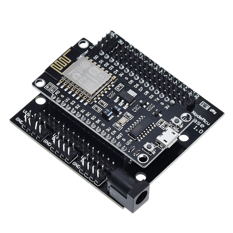
WHAT IS NODEMCU BASEBOARD?

WHAT IS POWER SUPPLY 12v5a?
⚡️ Deciphering the Power Supply: A Technical Guide to the 12V 5A Specification
A power supply labeled 12V 5A is more than just a transformer; it is a precisely engineered device governed by the laws of electricity and designed to safely convert alternating current (AC) into stable direct current (DC). Understanding this specification is crucial for safe operation, preventing equipment damage, and maximizing system efficiency.
I. Defining the Core Electrical Specifications
The two primary specifications on any DC power supply define the capabilities and limits of the source.
1. Voltage (12V): The Absolute Requirement
The Voltage (V), or electrical potential difference, is the fixed output requirement of the connected device.
Rule of Voltage Match: The voltage of the power supply must match the voltage requirement of the load (device). Connecting a 24V supply to a 12V device will almost certainly lead to catastrophic failure due to overvoltage.
Voltage Tolerance: While 12V is the nominal rating, high-quality power supplies maintain this output within a tight tolerance (e.g., 5% to ensure stable operation, regardless of the load's current draw).
2. Current 5A: The Capacity, Not the Output
The Current (A) rating is the maximum safe current the power supply is capable of delivering.
Current Capacity vs. Current Draw: A 5A supply will only output the current demanded by the connected load. If a CCTV camera requires 1.5A, the 5A supply will deliver only 1.5A, running at 30% capacity.
The Headroom Principle: It is industry best practice to choose a power supply with a current rating 20% to 30% higher than the device's maximum expected draw. This "headroom" prevents the supply from constantly operating at its limit, minimizing heat stress and significantly extending the lifespan of the unit.
II. Power and Efficiency Calculation
The fundamental relationship between Voltage, Current, and Power is defined by Ohm's Law and the power formula.
The rated Maximum Power Output P is calculated as:
For a 12V5A supply: 12VX5A=60 WATTS
This 60W figure represents the maximum power that can be safely delivered to the load. However, the power supply itself draws more than 60W from the AC outlet due to conversion losses inherent in the process. This leads to the concept of Efficiency (n), which is a key technical differentiator between models.

III. Architectural Types: Switching vs. Linear
The internal design dramatically affects the performance, size, and cost of the power supply.
Switching Power Supplies (SMPS): These are the modern standard. They rapidly switch power transistors on and off to regulate voltage.
Advantages: High efficiency, compact size, lighter weight, and wide input voltage range (e.g., 100V to 240V)
Disadvantage: Can generate high-frequency noise (EMI/RFI), which is a critical consideration for sensitive audio or radio equipment.
Linear Power Supplies: Older, simpler design using a transformer and passive components.
Advantages: Extremely low noise and ripple.
Disadvantages: Large, heavy (due to the large transformer), inefficient (wasted power as heat), and typically more expensive.
IV. Critical Safety and Polarity Considerations
Beyond matching specifications, safe operation requires attention to the final connection:
Polarity: DC power supplies have specific polarity (positive[+] and negative[-]). The standard barrel connector often uses Center Positive, meaning the inner pin is [+] and the outer sleeve is [-]. Reversing polarity WILL destroy most electronic devices.
Regulatory Compliance: The power supply must carry relevant safety marks (UL, CE, CCC) confirming it meets stringent safety and electromagnetic compatibility (EMC) standards for surge protection, over-voltage protection OVP, and short-circuit protection (SCP).
WHAT IS DUPONT WIRE?

🔌 Dupont Jumper Wires: Technical Standards and Prototyping Best Practices
The term "Dupont wire" is a widely adopted, yet generic, name referring to the ubiquitous jumper cables used in electronics prototyping. These cables are essential for creating temporary, solderless connections, primarily on breadboards and between development boards like Arduino and Raspberry Pi, and external modules. Their utility stems from adhering to a universal industry standard for header pin spacing.
I. Technical Specifications and Connector Standards
The core function of a Dupont wire relies entirely on its mechanical compatibility with the headers found on virtually all modern electronics development platforms.
1. The $2.54 mm (0.1-inch) Pitch
The critical, defining characteristic of a Dupont connector is its $2.54 mm (0.1-inch) pitch. This standardized center-to-center distance between the connector pins ensures perfect mating with:
Breadboards: The contact points (tie points) on a standard breadboard are spaced at $2.54 mm.
Header Pins: The male and female headers found on microcontrollers ($\text{MCU}$) and sensor modules adhere to this $2.54 mm pitch.
The actual connector style is technically referred to as an Amphenol FCI Mini-PV or a generic $2.54 mm rectangular connector.
2. Wire Gauge and Electrical Limits
The wire used in these assemblies is typically a thin gauge, which dictates their current capacity:
Wire Gauge: Most Dupont wires use a gauge between {AWG}22 and }28 (American Wire Gauge).
Current Rating: These thin wires are best suited for low-current signals (data) and low-power VCC GND connections (e.g., $5 V or $3.3 V logic. They are generally rated for approximately $3.0 A or less, but are not recommended for high-current applications (e.g., powering large motors or high-output LED strips), as the thin gauge and high contact resistance can lead to excessive heating and voltage drop.
II. The Three Essential Wire Configurations
The "Dupont" style is available in three primary termination types, each serving a distinct purpose in the prototyping workflow:
| Configuration | End 1 | End 2 | Primary Application |
| Male-to-Male ($\text{M} \to \text{M}$) | Pin (Solid) | Pin (Solid) | Breadboard to Breadboard: Connects two points on the breadboard or plugs into female headers (e.g., an Arduino shield socket). |
| Female-to-Female ($\text{F} \to \text{F}$) | Socket | Socket | Header to Header: Connects two male header pins, such as linking a sensor module to a microcontroller's GPIO pins. |
| Male-to-Female ($\text{M} \to \text{F}$) | Pin (Solid) | Socket | Bridging: The most versatile. Connects the Male pin on a sensor (Female end) to a Breadboard/Female header (Male end). |
III. Conductor Type: Solid Core vs. Stranded Wire
The choice of conductor material affects flexibility and longevity, a key consideration for advanced prototyping.
Stranded Wire (Most Common in Dupont Kits): Made of multiple fine wire strands twisted together.
Advantage: Highly flexible and resistant to metal fatigue from repeated bending, making it ideal for connecting separate modules or components subject to movement.
Disadvantage: The fine strands can separate when stripped, complicating insertion into breadboards or screw terminals without tinning (pre-soldering the tip).
Solid Core Wire (Often used for custom jumpers): Made of a single, rigid conductor.
Advantage: Holds its shape better, making it perfect for creating neat, permanent-looking jumpers on a breadboard. The rigid tip inserts cleanly.
Disadvantage: Prone to breaking if flexed repeatedly (metal fatigue).
For most DIY and introductory projects, the flexibility and convenience of stranded Dupont wires (often ribbon-cabled together) are preferred, making quick and reusable connections between the Arduino or Raspberry Pi and the breadboard.
WHAT IS ACCESS POINT?
📡 Wireless Link Mastery: An In-Depth Guide to Access Point (AP) Antenna Technology
The Access Point (AP) antenna is the most critical component in any wireless network, serving as the transducer that converts electrical energy into radio frequency RF waves and vice versa. Its design dictates the coverage area, signal strength, and overall data capacity of the entire Wi-Fi system. A robust understanding of antenna characteristics is essential for optimizing wireless performance.
I. Antenna Radiation Patterns: Shaping the Signal
The primary way antennas are categorized is by their radiation pattern—the graphical representation of how RF energy is distributed in three-dimensional space.
1. Omni-Directional Antennas
Pattern: Provides a 360 degree coverage in the horizontal plane Azimuth. The pattern resembles a flattened donut or torus .
Application: Best suited for open indoor environments (offices, homes) where users connect from all directions and the AP is centrally located.
Technical Trade-off: The 360 degree horizontal spread means the signal is compressed vertically Elevation. Higher gain omni-antennas have a very narrow vertical beamwidth and must be mounted carefully to avoid overshooting clients above or below.
2. Directional Antennas
Pattern: Focuses RF} energy into a concentrated, narrow beam. This focusing action results in a proportional increase in gain in the target direction.
Application: Ideal for Point-to-Point (P2P) links (connecting two buildings) or Point-to-Multipoint (P2MP) sector deployments (covering a specific section of a large area).
Types:
Yagi/Parabolic Dishes: Extremely high gain, narrow beamwidth for P2P links over long distances.
Sector Antennas: Cover a specific angular wedge (e.g., 90degree or 120^degree) for P2MP base stations.
II. Gain and Link Budget: The Mathematical Context
Antenna Gain is a crucial metric, measured in dBi (decibels isotropic). It is not a measure of power creation, but rather a measure of how effectively the antenna focuses the existing power.
Understanding dBi
The gain is always relative to a theoretical isotropic radiator (a perfect, single-point source that radiates equally in all directions).
Higher dBi} = Better Focusing: A higher gain antenna focuses the limited RF energy more intensely into a desired area, increasing the effective range and signal-to-noise ratio SNR.
The Power Trade-off: Increasing horizontal gain inherently reduces vertical beamwidth (or vice-versa), ensuring the Law of Conservation of Energy is maintained.
Role in Link Budget
Antenna gain is a primary factor in the Link Budget, the calculation used to determine the feasibility of a wireless link. The EIRP (Effective Isotropic Radiated Power) determines the maximum signal strength leaving the antenna:
In many regulatory domains (like the FCC, EIRP limits must be strictly observed to prevent interference.
III. Advanced Antenna Technologies
Modern Wi-Fi standards (like 802.11ac and 802.11ax rely heavily on multi-antenna configurations to achieve gigabit speeds.
1. MIMO and Beamforming
MIMO (Multiple-Input, Multiple-Output): Uses multiple antennas to transmit and receive several simultaneous data streams Spatial Streams over the same frequency channel. This multiplies the data throughput.
Beamforming (Transmit Focusing): An intelligent technique where the $AP manipulates the phase and amplitude of the signals sent from multiple antennas. The goal is to make the RF waves constructively interfere at the client's location, directing a focused, stronger signal specifically towards that device.
2. Polarization and Diversity
Polarization: RF} waves oscillate in a specific plane (e.g., vertical or horizontal). Mismatched polarization between the AP and client can cause a significant drop in signal strength.
Antenna Diversity: The AP is equipped with two or more antennas and constantly monitors the incoming signal quality from each. It dynamically selects the antenna with the highest SNR for receiving, significantly improving link reliability in environments with high multipath interference (signals bouncing off objects).
By carefully selecting antennas based on their radiation pattern, gain, and supporting MIMO technology, network engineers can custom-tailor wireless coverage to meet the exact performance and density demands of any environment.
WHAT IS UNIVERSAL COINSLOT?
🪙 The Universal Coin Acceptor: Principles of Coin Validation and Digital Interface
The universal coinslot (more accurately termed a multi-coin acceptor) is a sophisticated electronic device that serves as the critical financial gateway for unattended automated machines, ranging from arcade games and laundromats to modern PISO Wi-Fi vending systems. Its "universality" stems not from accepting every coin globally, but from its programmability and ability to be quickly adapted to multiple coin profiles within a specific currency family.
I. The Physics and Electronics of Coin Validation
Before a coin is accepted, it must pass a rigorous, multi-stage electronic validation process to differentiate genuine currency from slugs or foreign objects. This process is typically performed by a microprocessor within the acceptor unit.
1. The Validation Tunnel
As a coin rolls through the acceptor's internal tunnel, it is subjected to several checks:
Size (Diameter and Thickness): Mechanical guides and optical sensors measure the physical dimensions. If the coin is outside the configured tolerance, it is immediately rejected.
Material (Inductive Testing): The coin passes through inductive coils which generate a high-frequency electromagnetic field. The presence and material composition of the coin (e.g., copper, nickel, or steel) alter the field's frequency and amplitude. The microprocessor measures this change and compares the electromagnetic signature to stored, calibrated profiles.
Time and Speed: The time it takes for the coin to roll between two sensors is measured. This ensures the coin is moving at a natural speed and helps to detect fraudulent techniques like "stringing."
2. Calibration and Training
For a coinslot to be truly "universal" within a region, it must be trained (calibrated). The operator places several samples of a new coin (e.g., ₱5) into the acceptor to record its precise physical and electromagnetic signatures. This creates the unique, digital coin profile that the acceptor will use for all future transactions.
II. Interfacing with the Control System
Once a coin is validated, the acceptor must communicate the value to the host machine (e.g., a microcontroller like an Arduino or a dedicated timer board). This is achieved through standardized electronic interfaces.
1. The Pulse Interface (The PISO Wi-Fi Standard)
This is the most common interface for simple vending applications due to its simplicity.
Mechanism: When a coin is accepted, the acceptor sends a defined electrical pulse (a momentary 5V signal) to the host machine.
Value Differentiation: To handle multiple denominations (e.g., ₱1, ₱5, ₱10), the system can be configured in two ways:
Multiple Pulses: A ₱5 coin might generate five distinct, rapid pulses, while a ₱1 coin generates one pulse.
Multiple Outputs: The acceptor uses separate parallel output pins (Output 1 for ₱1, Output 2 for ₱5, etc.) to signal the host.
2. Serial Interface (Advanced Systems)
For high-security or complex transactions, a serial interface (like RS-232) is used. This allows the acceptor to transmit an entire data packet, including the exact coin type, transaction ID, and fraud status, rather than just a simple pulse.
III. Anti-Fraud and Durability Features
Modern multi-coin acceptors incorporate features designed to maintain revenue integrity in unattended public settings.
Anti-Stringing Mechanism: Physical mechanisms inside the chute prevent a coin attached to a string or wire from being inserted and retrieved repeatedly.
Coin Return Solenoid: A dedicated coil or motor is used to actively reject foreign objects, bent coins, or coins that fail the validation checks, ensuring the machine does not jam.
Durability and Environmental Rating: Units designed for outdoor vending or high-traffic arcade environments are often sealed and feature robust metal construction to resist tampering and withstand temperature fluctuations and humidity.
The universal coinslot, therefore, represents a precise electromechanical payment system essential for the proliferation of coin-operated micro-enterprises.
WHAT IS LED FRAME RGB COINSLOT?
✨ The Intelligent Interface: Technical Analysis of the LED Frame RGB Coinslot
The LED Frame RGB Coinslot is a product of modern Human-Machine Interface HMI design in automated vending. It integrates three distinct components—a coin validation unit, an RGB lighting system, and a decorative bezel—to create a functional, visually communicative, and highly attractive point of sale. This integration is critical for maximizing user engagement and, consequently, transactional throughput in unattended machines.
I. Technical Integration: Coin Acceptor and Illumination
The sophisticated behavior of the RGB frame is directly tied to the status of the coin acceptor, which requires precise electronic communication.
1. Communication Protocol
The illumination unit is not a passive light; it is driven by a control signal from the host machine or the coin acceptor's internal microcontroller.
Host Control: In systems like PISO Wi-Fi (which use a dedicated timer board), the host sends a digital signal to the RGB frame. This allows for complex, context-sensitive illumination sequences.
Simple Control (Built-in Logic): In simpler designs, the RGB frame's color might be triggered directly by the coin acceptor's pulse output. For example, the frame might remain solid white (idle) and flash green (pulse received) when a coin is accepted.
2. The Power of RGB Signaling
The Red, Green, Blue RGB color model allows for millions of colors, but in the context of vending, colors are used as universal signifiers of machine status, significantly improving user experience UX:
| Color/Pattern | Machine Status | User Interpretation |
| Pulsing Blue | Idle / Ready | Machine is powered on and awaiting coin insertion. |
| Flashing Green | Coin Accepted / Validated | Transaction successful; machine is starting service. |
| Solid Red | Error / Full / Offline | Do not insert coins; system fault or coin box is full. |
| Alternating Colors | Service Active | Service is running (e.g., Wi-Fi time is counting down). |
This dynamic signaling replaces static light-up indicators, providing clearer, more immediate feedback.
II. Application in the Vending and Gaming Industry
The use of dynamic RGB coinslots is driven by two key commercial objectives: attraction and instruction.
1. Commercial Attractiveness and Impulse Buying
In competitive environments (such as arcades or a street lined with PISO Wi-Fi machines), the visual appeal of RGB lighting serves as a powerful magnet.
Aesthetic Appeal: The shifting, dynamic light is designed to catch the peripheral vision, triggering a psychological response that draws potential customers toward the machine.
Perceived Value: The inclusion of advanced lighting often makes the machine appear modern, well-maintained, and high-tech, subtly justifying the service cost in the user's mind.
2. Functionality in Unattended Systems
For unattended systems like PISO Wi-Fi machines, the visual instruction provided by the RGB frame is critical for reducing service calls and confusion.
Draw-in Focus: The lighting focuses the user's eye directly onto the most critical HMI point—the coin insertion slot—reducing the time it takes for a user to initiate a transaction.
Anti-Fraud Deterrence: Some advanced systems can be programmed to flash a specific color upon detecting a "slug" or fraudulent coin (identified by the acceptor's anti-fraud sensors), providing an immediate, silent alert to the user and nearby operators.
The LED frame RGB coinslot is thus an optimized piece of hardware, fusing the essential function of payment acceptance with the psychological power of dynamic light to enhance security, communication, and profitability.